
English is not my mother tongue, this page may contain incorrect words or sentences.
urriellu.net => Projects => Electronics => CLK³
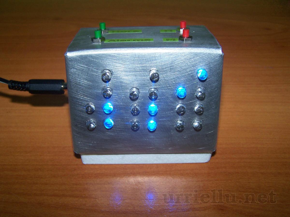 CLK³ is a binary alarm clock built completely from scratch, based on a PIC16F877A microcontroller and application written in assembly language.
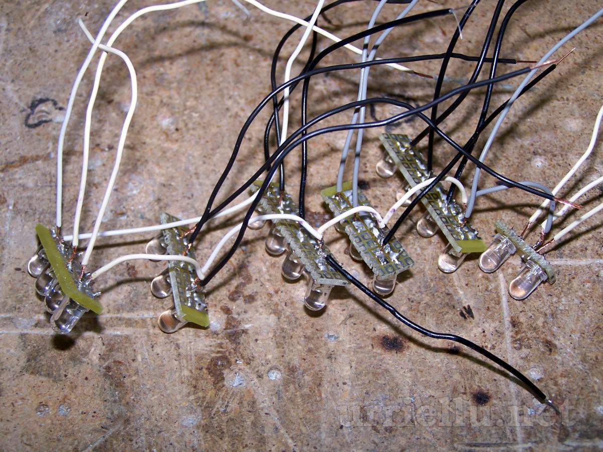
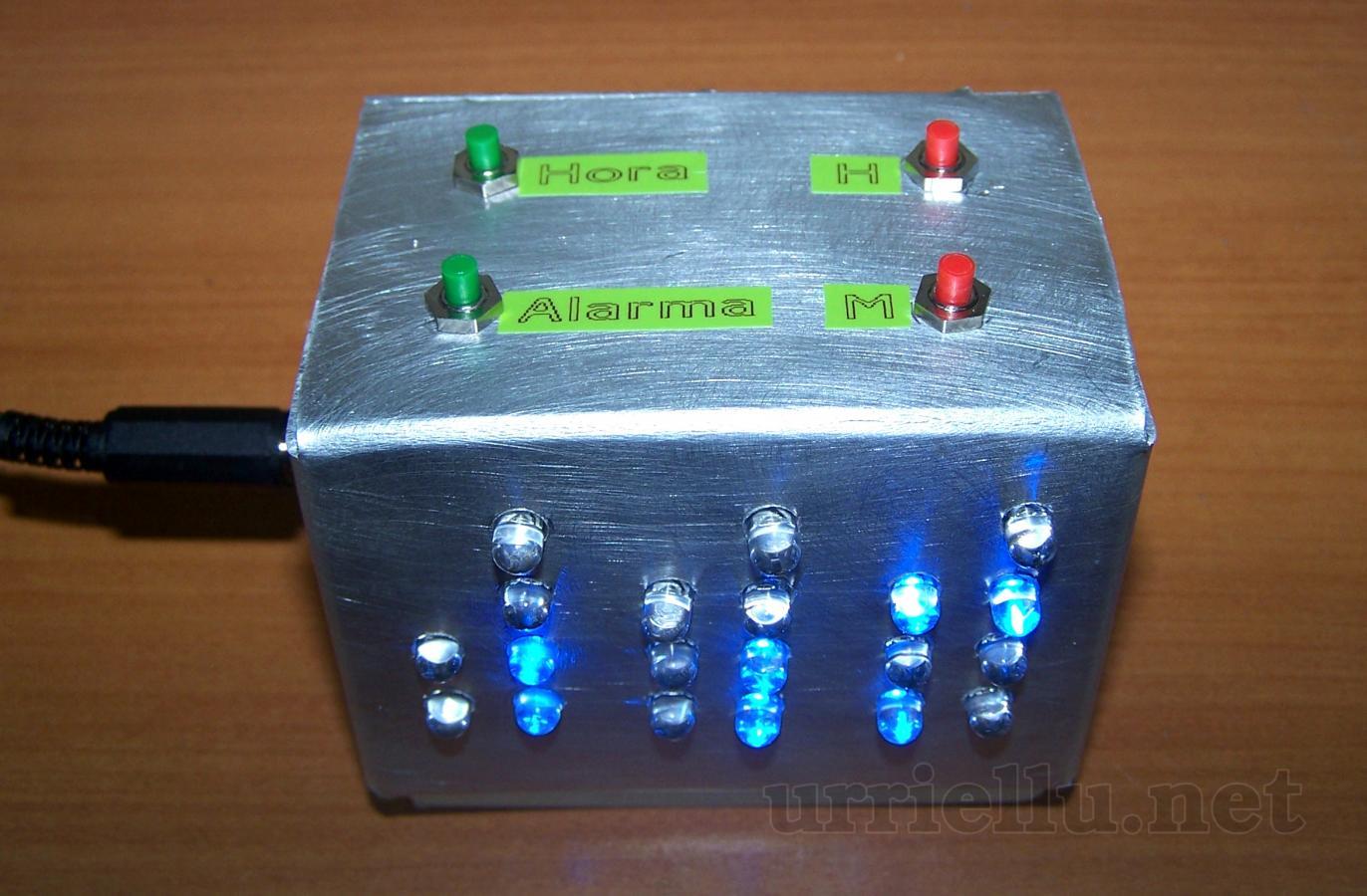
Actual time (and time set as alarm while it's being configured) is shown in BCD by 20 LEDs [how to read it].
The time and alarm are configured by four push-buttons as in any other commercial alarm clock.
It's powered by an external power supply unit. 7-35VCC are allowed.
This is the first electronic circuit I designed from scratch, my first time programming a MCU, the first time I wrote an application in assembly language and my second homemade PCB. Usually people starts building very simple things and they increase the complexity of their work a bit at a time, but I prefer to learn and build things much more complex than I am (theoreticaly) capable of, so I learn and work much more faster.
Electronic circuit
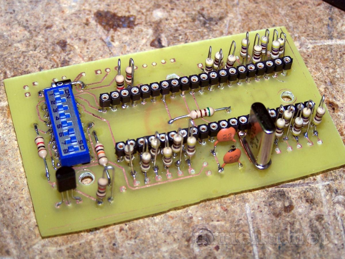
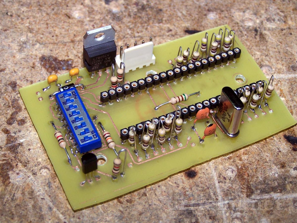
 Input 7-35V is converted to 5V using a LM7805. The MCU can be programmed by ICSP plugging the programming cable to P2 and activating positions 6 and 7 of S5 and deactivating the rest of them. For using the circuit in clock-mode (not programming-mode) positions 1-5 of S5 must be activated and 6-7 deactivated.
LEDs used to show the hours are connected to PORTA, those used to show minutes to PORTC and for seconds to PORTD. Button S1 rises the time one hour, S2 one minute, S3 sets up the actual time and S4 the alarm time.
Note: The resistor connected to the base of Q1 is too small.
The diode D21 seems to be upside down but it isn't because P1 is the power jack, so current must flow from the GND of the circuit to P1-1 which is the ground of the external power.
The circuit has two ground lines: GND and Vss. Usually (clock-mode) they are shorted but they are split when the PIC is being programmed so Vss (ground of the ICSP programmer) is completely isolated from the rest of the circuit.
The circuit has been designed using Altium Designer 6.
Application/firmware
Note: the source code is in spanish.
clk3.asm, 435 lines [download]
- ; CLK[cubo]
- ; por Adrian Bulnes [Urriellu]
- ; clk3 @ urriellu . net
- ; Aviso: todos los comentarios estan escritos sin tildes porque MPLAB solo soporta archivos en ASCII (y en teoria tambien UTF16, pero no esta bien implementado y su uso es inutil, culpa de Microchip ;-)
- LIST P=16F877A, R=hex, W=-302, W=-208 ;elegimos modelo de PIC, raiz hexadecimal, eliminamos avisos 302 (registros en bancos !=0) y 208 (etiquetas demasiado largas)
- INCLUDE P16F877A.INC
- __CONFIG _CP_OFF & _WDT_OFF & _PWRTE_ON & _HS_OSC & _LVP_OFF & _DEBUG_OFF & _WRT_OFF & _CPD_OFF & _BODEN_ON ;mirar el archivo de cabecera. Brown-Out Reset activado para que ante caidas de tension no siga funcionando y que se consideren algunos botones como pulsados
- ;aliases para pines
- PuertoAlarma EQU PORTB
- BitAlarma EQU 1
- PuertoPulsadores EQU PORTB
- [...]
With a 20MHz oscillator each instruction is executed in 200ns and setting the prescaler of TMR0 to 64 you get 0.0000128s (12.8μs) intervals between values of TMR0. Each time TMR0 overflows an interrupt is thrown, and this happens after 256 TMR0 intervals, that is, after 3276.8μs (3.2768ms). If 305 TMR0 overflows (interrupts) are counted we'll get time divisions of 999.424ms (0.999424s). Now if we count 45 more intervals of TMR0, each one of 12.8μs, preloading TMR0 to 211, plus those 305 TMR0 overflows we can execute one function exactly each second.
305 times x 0.0032768s + 1 time x 45 intervals x 64 [prescaler] x 0.0000002s = exactly 1 second
But the clock is not as precise I wish it were because the oscillator isn't precise either, so the instructions aren't executed exactly each 200ns and after 24 hours the clock is offset by a few minutes.
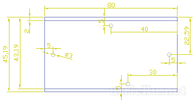
Box
The box was built using a 2mm (0.039") thick aluminium panel, bended to become an irrecular box, so the front side (where LEDs are placed) is slightly facing up and the time can be read easier.
Its plans were drawn using AutoCAD 2006. All the lenghts are in millimeters.


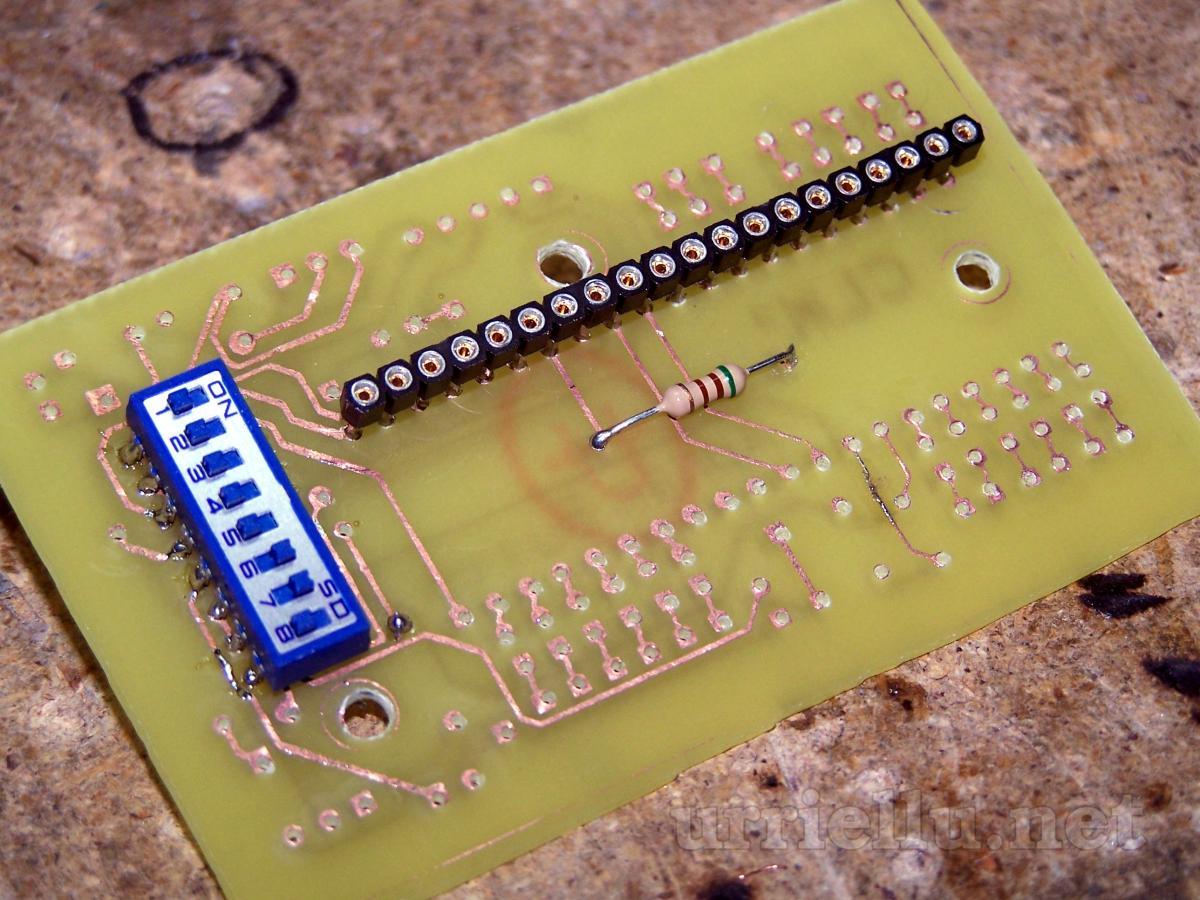
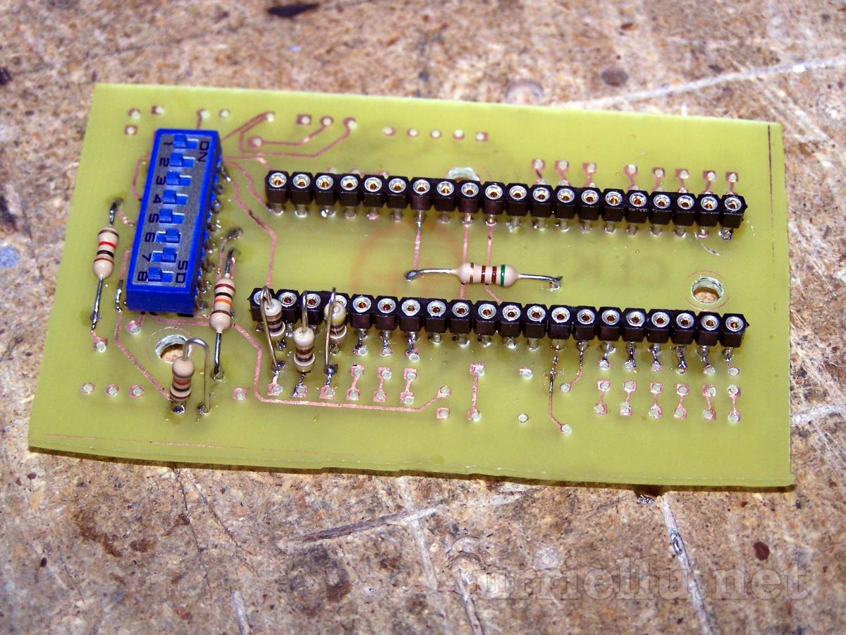
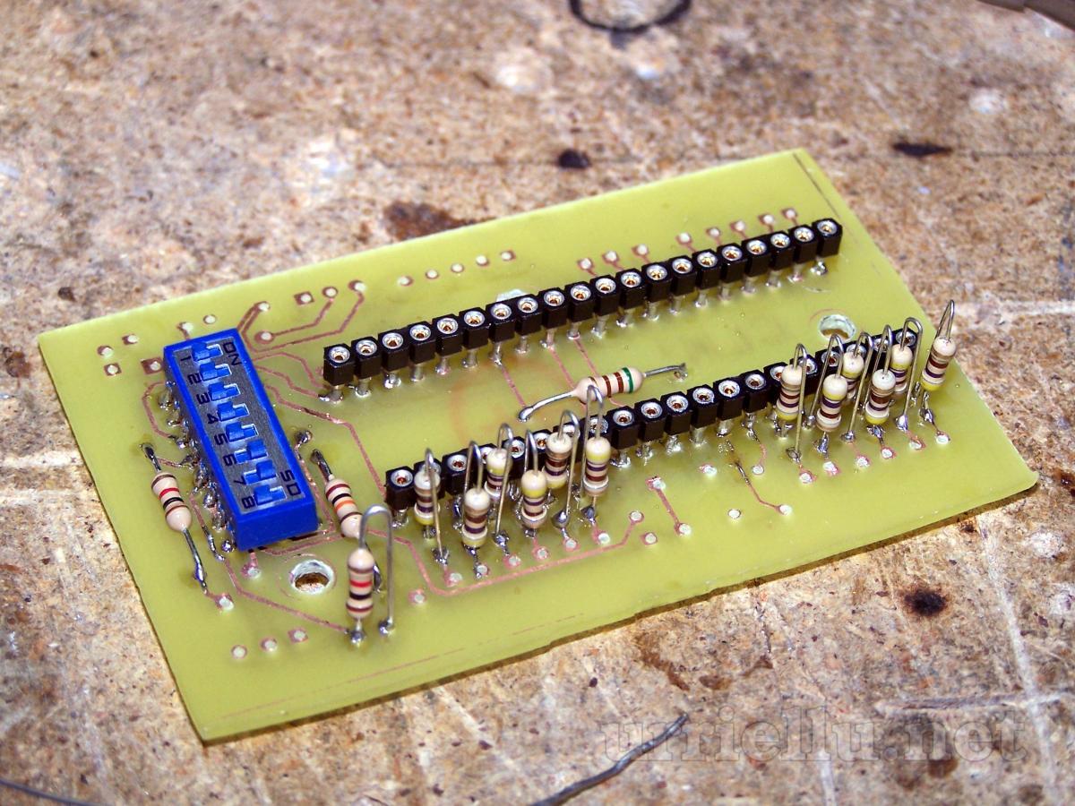
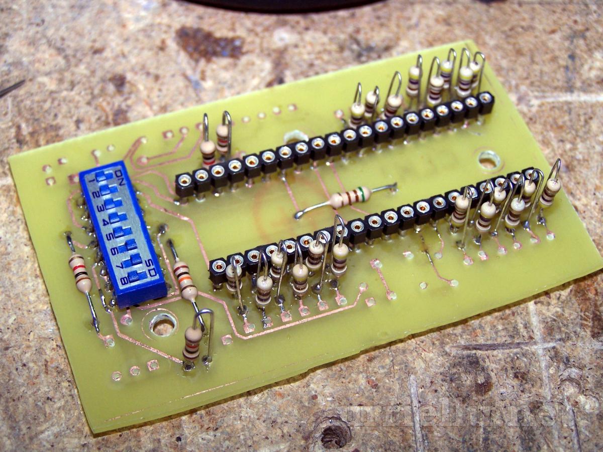
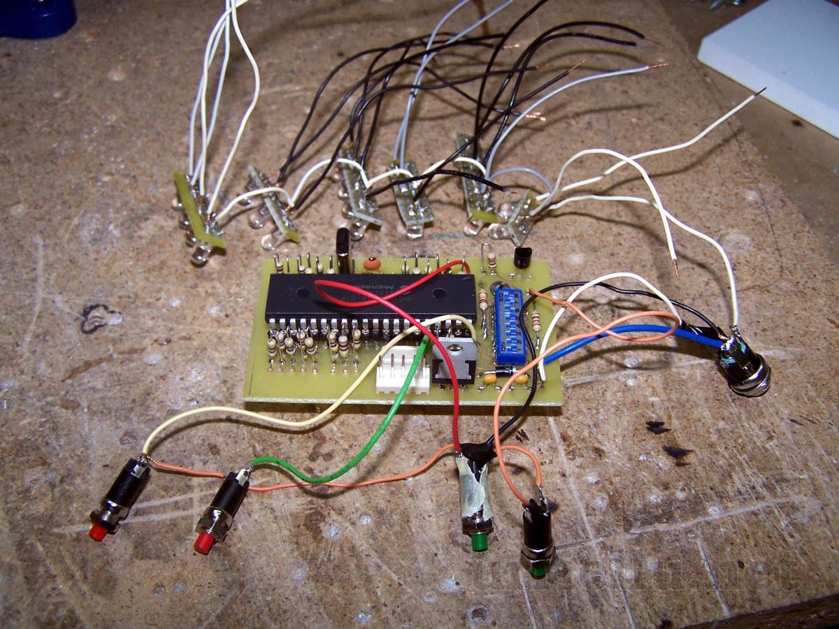
PCB


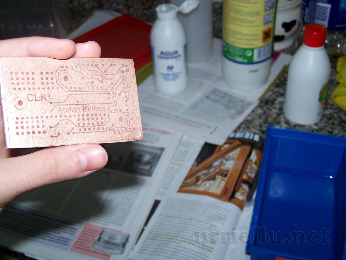
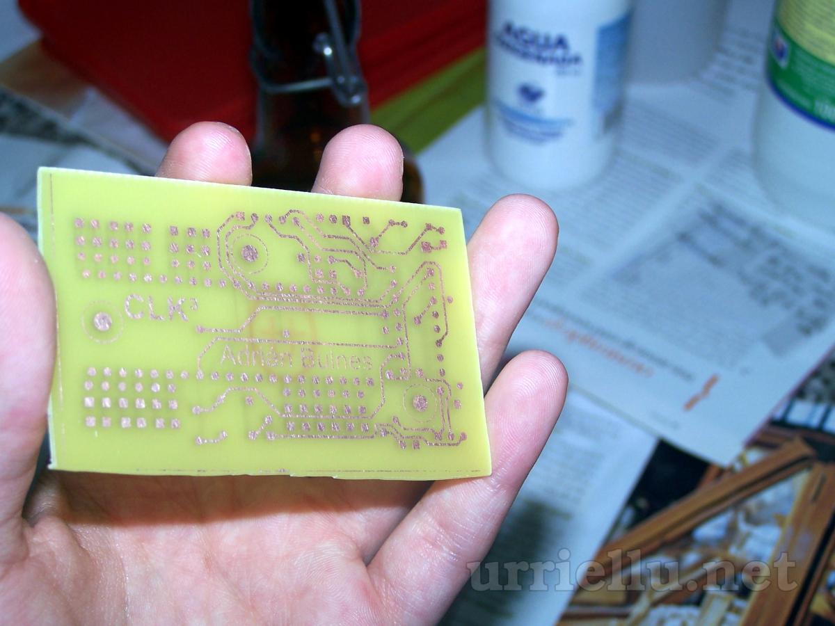
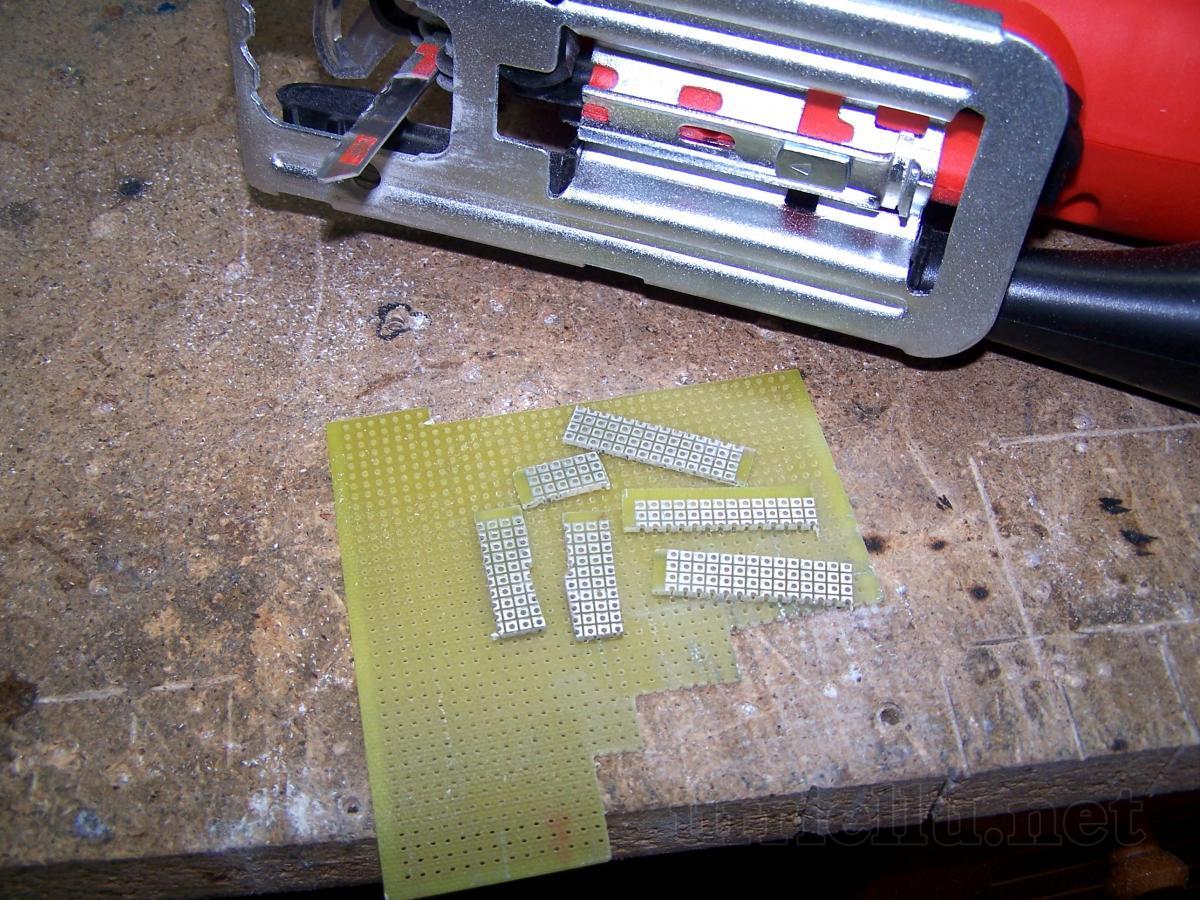
Building the circuit


Finished clock

Vídeos
Video of the binary clock working without its box. Intervals between seconds seem to be irregular but this is a camera problem (it's designed for photos, not for videos), the real mistake made by the oscillator can't be seen.
- Download AVI (XviD + MP3 LAME) [10.05MiB]

ProjectsElectronicsCLK³pic³progMechatronicsSoftwarePigmeoOthermabxArticlesElectronicsSoftwareOtherAdvantages of C#Events2nd (inter)Universitary Free Software ContestMicrobotics championship at the University of Oviedo. Summer 2007About urriellu.netThis websiteAbout mePublishing licensesContact
languageespañolrot13morse codebrailleenglishrot13morse codebraille
